Connecting 6 or more new properties to our network.
If you are looking to connect six or more new lots, set up industrial, or large-scale commercial connections to the Counties Energy network, the following information is for you.
If you wish to connect six or fewer lots to our network, please click here.

We can offer two options to meet your requirements: a high-level assessment or a detailed design and quote. Please review the information to determine which option is relevant for you.
HIGH-LEVEL ASSESSMENT
- A High-Level Assessment involves a desktop investigation to provide a financial estimate for budgetary purposes, this excludes a reticulation plan.
- The Customer can expect to receive this assessment 10-15 business days after receiving acknowledgment of your request.
- You can fill out the form here.
FORMAL DESIGN AND QUOTE
- A detailed reticulation plan and contract agreement will be provided with a validity of three months upon completion of the full-detail design.
- We offer Connection Design Requirements to ensure all relevant documentation is submitted for review.
- A non-refundable design fee of $5,500.00 excl GST is payable to proceed to the detailed design stage. Payment instructions will be communicated after the application is submitted.
(Note: Design fees will allow CEL to produce detailed design and price and issue a formal Contract Offer) - Upon receiving the application and payment of the design deposit, an invoice will be issued as a receipt of payment.
- Your application will be reviewed by a Design Engineer, and you can expect to be contacted for project initiation within 10 business days.
- The expected lead time for design and quotation is subject to the complexity and will be advised when all relevant information has been reviewed. Typically, this timeframe is at a minimum 8 weeks.
- You can find the form below after accepting all terms shown.
NOTE: If there is no response from the requester for a period of four (4) weeks following numerous attempts by the designer to establish contact, the project will be closed. Since the design fee is non-refundable, a new application will be required and a new design fee to be paid.
If the customer communicates any delays (such as consent issues, etc.) that result in the project being on hold for a consecutive period of 4 weeks, the project will be closed, and the customer will have 3 months to re-initiate it. A new project number will be assigned, and the design fee from the previous project will be carried over. Re-initiation may only occur once during the process. If the project has not progressed for more than 3 months, a new application will need to be submitted via the website and a design fee will be applicable.At Counties Energy, we’re working with the Electricity Networks Association (ENA) and other Electricity Distribution Businesses (EDBs) to simplify the connections process for customers.You can check out the glossary here to better understand the terms related to connections and pricing.
DESIGN REQUIREMENTS – 0800 100 202
All new sub-divisions of residential lots, industrial or commercial connections as an extension onto the Counties Energy network are subject to a design and quote to provide the relevant electricity connection point(s).
If you are subdividing, building, or installing equipment that greatly increases your power use, you may be required to pay a capital contribution. This is your contribution towards any addition or upgrade of the network near your site needed to meet your needs and towards the impact of that site on the network as a whole. See the full Capital Contribution Policy here.
Following receipt of all relevant information, the expected lead time for design and quotation is subject to complexity and will be advised once an application has been reviewed. Typically, this timeframe is at minimum 8 weeks.
At the end of the design stage, you will receive a contract and associated documents. The contract would typically be valid for 3-months from the date of issue.
The Customer should allow 6 months from receiving full contract acceptance, for Counties Energy to engage a Contractor and order the required materials.
Long lead item procurement is circa 7-9 months from the date of order.
The following information is required before the design can commence:
1.0 Complete the online form using the following link: Application Form
2.0 Full site plan for the proposed development (or stage) in CAD format – this may include the expected Network Point of Connection location(s).
For Subdivisions, the following must be included in the CAD format site plan:
2.1 All driveway Locations – Counties Energy standard is to have a service pillar at the boundary between two properties (avoiding driveways).
2.2 All streetlight Locations – the subdivision streetlighting layout is required for the design and would ideally have approval from the relevant Local Authority.
2.3 Retaining Walls – highlight any retaining walls in the CAD file and the scheme plan in the subdivision. It will enable the designer to design efficiently to cater for service main connection(s).
2.4 All commercial Network Point of Connection location(s) – include load requirements, e.g., pump stations, traffic signal supplies,etc.
2.5 Road Back Berm detail for every road (including JOALS / ROWs) – specifically, we need to know if any proposed roads do not meet our requirement. A minimum of 600mm wide grass Back Berm (electricity cables sit within the grass Back Berm at a distance of 400mm from the property Pillars are installed circa 100mm off the boundary in the grass berm).

Minimum clearances 1 x HV And / Or 1 x LV in shared utility trench within road reserve footpath central (Preferred Option)

Minimum clearances 2 x HV And / Or 2 x LV in shared utility trench within road reserve footpath central (Preferred Option)
2.6 Development/stage boundaries marked – each proposed Lot requiring a residential Network Point of Connection should be marked.
2.7 Builders Temporary Supply (BTS) – Developer/Requester to discuss the BTS requirements within the early stage of design and quote.
3.0 Confirmation if streetlights each have an integrated photocell sensor switch that turns them off and on based on daylight. There would be a significant additional cost if the streetlights do not have an integrated photocell sensor switch and need to be centrally controlled via a relay.
4.0 Confirmation that the developer’s appointed civil contractor will carry out all trench work within the development. It is standard for the developer’s appointed civil contractor to provide a common service trench for utilities and subsequent backfill once utilities are installed ‘within the development boundary’. The attached Subdivision HV and LV Duct & Cable Per-Section installation requirements would form part of the contract.
5.0 110kV relocation projects can take circa 18-24 months for design and delivery, depending on the project complexity. The timeframes will be discussed in detail with the respective designer during the detailed design process.
Note: Any changes to the design, including revised lot layouts, submitted after the application may require a complete redesign of the project. These changes must be clearly reflected in an updated CAD file. The Design Engineer will assess the impact of the revisions on the project timeline and confirm any adjustments to the expected quote delivery date. Depending on the complexity of the changes, a new design fee may apply. This will be determined on a case-by-case basis.
Considerations:
- If a transformer (<1000kVA) is required for the development, a 6.3m x 4.6m set-out area, free of all other utilities, would be This may be via an easement if there is not enough space in the ‘to be’ vested road.
- If a HV Ring Main Unit (RMU) is required for the development, a 5.0m x 4.0m set-out area, free of all other utilities, would be This may be via an easement if there is not enough space in the ‘to be’ vested road.
- If both a transformer (<1000kVA) and a HV RMU are required at the same location within the development, an 8m x 4.6m set-out area, free of all other utilities, would be required. This may be via an easement if there is not enough space in the ‘to be’ vested road.
- All new LV connections (rated up to 160A) to Counties Energy’s network shall be made via a pillar box as per the Distribution Code.
- Supplies to urban installations shall be single phase, unless otherwise agreed by Counties Energy.
- Supply to rural dwelling installations is recommended to be three phase and shall be a minimum of two phase with the connected load, balanced across all connected phases at the Main Switchboard.
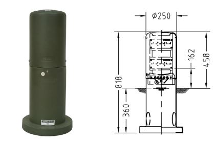
Standard Pillar
- Service Pillar – EP2
- Link Pillars
- 3-Way Pillar: 500mm x 900mm x 350mm
- 4-Way Pillar: 500mm x 900mm x 350mm
- 5-Way Pillar: 600mm x 900mm x 350mm

Cable installation through Bridges
The preferred option is to have cables installed within bridges, PE or PVC ducts (continuous) are to be concreted in place, 250 mm concrete cover minimum from the top of ducts. Concrete strength to be at least 20 MPa. This depth needs to be agreed upon during the construction of the bridge.
For existing bridges, where possible, cables are to be thrust under the bridge. If this is not possible, cables can be installed underslung. When installed underslung, cables are installed within orange PE or PVC ducts which are installed inside an outer steel sleeve to provide mechanical protection.
Sleeve Requirements:
The sleeve, and fittings shall be designed to last, with no or minimal maintenance for the life of the asset within. This is, on average, 55 years; as such, 316 stainless steel fittings and sleeves are to be used as a minimum.

Note 2—If PVC duct is used, the Inner diameter of the sleeve will need to accommodate the socket of the PVC duct; thus, a minimum of 200mm (ID) sleeve shall be used.
Separation requirements – Ground-mounted Distribution Transformers, RMUs, and buildings
a) Ground-mounted transformers
i) Transformers shall be located a minimum of 1.5m from buildings or firewalls.
1.8 m clearance shall be allowed on the sides of the transformer with doors to enable the door to open and allow for egress in an emergency.
ii) Adjacent building walls within 3 m of the Ground-mounted distribution transformers shall have a Fire Resistance Rating (FRR) of 120 min or more
iii) Adjacent building walls within 7.5 m but greater than 3 m shall be constructed using non-combustible materials
iv) No additional FRR requirements for buildings beyond 7.5 m

b) On sites where multiple transformers are in operation, they shall be at least 3m apart
c) If the clearances in clauses (a), (b) and (c) can’t be met, a firewall with a minimum 120 min FRR shall be constructed between the transformer and the building or transformer.
d) RMUs are to be located a minimum of 1m from the buildings and transformers.
e) Buildings or fences with metallic surfaces may require more significant separation to the distribution assets to mitigate against transfer potentials hazards.
Using clause 2.3. from ECP 34 Electrical Safe Distances as a guide, a minimum of 2.2 m separation shall be allowed between distribution transformers and fences. Where this separation can’t be met, a site-specific design may need to be carried out.